AГЛИЙСКИЙ. Пособие по английскому языку для машиностроительных вузов допущено Министерством высшего и среднего
 Скачать 1.36 Mb. Скачать 1.36 Mb.
|

|
MECHANICAL TOOLS Both in maintenance and in repair of machines all kinds of fitting operations are applied. An important role is played by disassembling and assembling operations. Special instruments are used for performing these operations. Among the variety of mechanical tools: used for disassembling and assembling machine parts and in their repairing are wrenches (Fig. 10). According to their construction and application wrenches may be of different types: single- ended 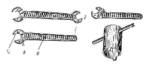 Fig. 10 Wrenches: Fig. 10 Wrenches:1 — single-ended wrench (a — handle; b — head; с —span); 2 — double-ended wrench; 3 — adjustable wrench; 4 — socket wrench and double-ended nut wrenches, adjustable wrenches, socket wrenches and special wrenches. A nut wrench is used for screwing and unscrewing nuts. It consists of a handle and a head with an opening known as the span. Adjustable wrenches may be used for unscrewing nuts and bolts of different dimensions. Socket wrenches are applied in cases when nuts or bolt heads located in recesses are hardly accessible for a nut wrench. Special wrenches are used for unscrewing and screwing nuts of a definite type. Wrenches are used: by drivers for repairing cars, in locksmith's shops and fitter's shops. Fitters use them to screw different types of machine parts as: washers, bolts, shafts, etc. Plumbers use them to repair pipes, taps, etc. Besides different types of wrenches there are round pliers or needle, nose pliers which are widely used by locksmiths, electricians and other specialists for gripping, screwing or cutting off thin metal and wires. Exercises I. Use the following words and phrases in sentences of your own: nut, to screw, to maintain, to unscrew, to assemble, to disassemble, nut wrench, adjustable wrench, Socket wrench, to grip, plumber, electrician, fitter II. Answer the following questions: 1. What operations are applied in. maintenance and repair of machines? 2. What instruments are used for disassembling and assembling machine parts? 3. How are wrenches subdivided? 4. What is a nut wrench used for? 5. When are adjustable wrenches applied? 6. In what cases are socket wrenches used? 7. What wrenches are used for screwing and unscrewing nuts? 8. By whom are different wrenches used? 9. What other mechanical tools can be used in repairing? III. Find in the text nouns for the following verbs: to maintain, to operate, to construct, to fit, to assemble, to apply IV. Supply -antonyms for the following words: disassembling, to screw, difficult, single-ended, accessible V. Supply synonyms for the following words: to locate, to grip, widely, different, dimensions VI. State the functions of alt, the -ed forms and translate the following sentences into Russian: 1. Wrenches used to unscrew and screw nuts are known as adjustable wrenches. 2, Different wrenches are used to? screw different types of. machine parts, such as washers, bolts and shafts. 3. Locksmiths and fitters use special instruments depending on the parts of machines to be disassembled and assembled. 4. Nut wrenches may be used for screwing different nuts. 5. Tools called "wrenches" are used -for turning bolts and nuts. 6.: Tools known as S-wrenches, angle wrenches, etc. are named so according to their shape. 7. the wrenches may also be named from the object on which they are used. 8. Adjustable wrenches are named so because they may be applied for screwing and unscrewing bolts and nuts of different sizes. VII. Translate the following sentences into English: 1. Обычно механические ключи, используемые при ремонте разнообразных деталей, изготовляются из прочной стали. 2. Кусачки могут применяться для операций, выполняемых слесарями. 3. Торцовый ключ может применяться для завинчивания гаек, расположенных в углублениях. 4. Слесарь часто пользуется инструментами, называемыми разводными ключами. 5. Среди многих инструментов, применяемых электриками, есть круглогубцы.
A. MEASUREMENT The size and shape of all machine parts should be in accordance with the corresponding drawing. The produced parts should be checked by means of measurement, which generally involves comparison either with some accepted standard or with a mating part. The significance of any measurement is determined by the degree of accuracy to which the parts may be measured. Depending on measurements different measuring tools can be used such as rules, slide gauges, vernier calipers, depth gauges, dial indicators, micrometers, clearance gauges, inside and outside calipers, plug gauges, bevels, universal protractors, etc. B. MEASURING TOOLS When accurate measurement of the part is required, the vernier calipers, micrometers and slide gauges are used. When it isnot so important to have an accurate measurement of the part, metal rules, inside calipers and outside calipers will do. 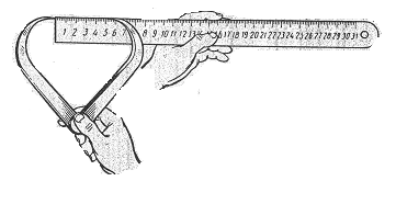 Fig. 11. Steel Rule Fig. 11. Steel Rule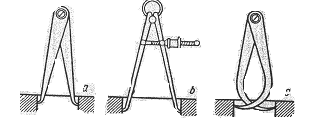 Fig. 12. Calipers: a — inside; b — spring; с — outside Steel rules (Fig. 11) serve for determining the length and sometimes is the depth of the part to be measured. Steel rules are graduated in millimetres, but in the USA and England they are graduated in thirty-seconds and sixty-fourths of an inch.1 The outside (Fig. 12) calipers are the simplest instruments for measuring external diameters of the part. The outside caliper consists essentially of two curved legs. The inside calipers are used for determining the internal diameters of the part. Its construction is almost similar to that of the outside calipers. Sometimes the outside calipers may be used for measuring internal diameters of the part. The outside and inside caliper measurements may be read by placing the legs of the calipers on a rule and placing one leg and the end of the rule against a flat surface as shown in Fig. 11. 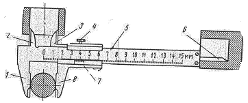 Fig. 13. Vernier Calipers: Fig. 13. Vernier Calipers:1, 2, 3, 8 —jaws; 4 — adjusting screw; 5 — primary scale; 6 – depth rod; 7— frame with vernier 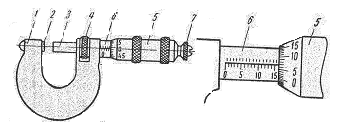 Fig. 14. Micrometer: Fig. 14. Micrometer: 1 — frame; 2— anvil; 3 — spindle; 4 — lock nut; 5 — barrel; 6 — thimble; 7 — ratchet thimble Vernier calipers (Fig. 13) can be used for measuring both external and internal sizes of a part. By using vernier calipers measurements up to .001" may be determined. Vernier calipers consist of a primary steel scale and four jaws. Jaws 1 and 2 are integral with the scale. Jaws 8 and 3 are attached to the frame sliding along the scale. The frame may be clamped on the scale in any position by means of an adjusting screw. External surfaces may be measured with jaws 1 and 8, while internal surfaces are measured with jaws 2 and 3. The depth of recesses is measured with a depth rod 6. A vernier onthe frame 7 serves for measuring fractional parts of a millimetre. The micrometer (Fig. 14) is an instrument for precise measurement of length and thickness of a part to one ten-thousandth of an inch. The principle of operation is similar to that of vernier calipers. A graduated thimble serves as the primary scale. The scale on the barrel of the micrometer is used for the vernier reading. The part to be measured is placed between the anvil and micrometer screw, which is 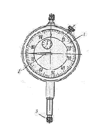 Fig. 15. Dial Indicator: Fig. 15. Dial Indicator:1 — dial; 2 — indicator pointer; 3 — test point; 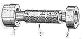 Fig. 16. Go and No-Go Plug Gauge Fig. 16. Go and No-Go Plug Gauge1 — go plug gauge; 2 - handle; 3 — no-go plug gauge called a "movable spindle". By rotating the thimble, the spindle is removed or approached to the anvil. By rotating the ratchet thimble the spindle is moved and thus the part is pressed to the anvil. Thereupon the rotation of the ratchet thimble is discontinued, the micrometer opening is fixed by the lock nut and the reading is taken. The micrometer reading is the sum total of the barrel divisions, the thimble divisions with respect to the axial line on the barrel, and the vernier reading. Fig. 15 shows a dial indicator. The dial indicator is a gauge with a graduated dial and an indicator pointer connected to a test point by a system of levers. Any movement, of the test point is magnified by the indicator pointer. The dial indicator is used to check the shape of a part, the precision of its machining, as well as for checking the accuracy of cutting machines. Thread plug gauges ox internal gauges, being of "go" and "no-go" type (Fig. 16), are generally used for testing threads or tapped holes. Depth gauges are used for measuring the depth of grooves and holes. Their principle of operation is similar to that of vernier calipers. A primary scale sliding in a frame may be locked in any position by a screw. The depth of a groove or a 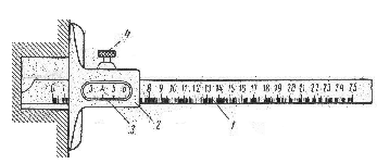 Fig. 17. Depth Gauge: Fig. 17. Depth Gauge: 1 — primary scale; 2 — frame; 3 — vernier; 4 — screw hole is measured by means of the primary scale and a vernier as shown in Fig. 17. Conical surfaces are measured with control gauges. A universal angle gauge for measuring internal and external angles is shown in Fig. 18. The universal angle gauge consists of a base with a primary scale attached to the base. A triangle may be attached to the quadrant by means of a holder. In its turn a detachable rule: is attached to the triangle. The triangle and the detachable rule can be moved along the face of the quadrant. Angles can be measured within the range of 0° to 320° by means of the universal angle gauge. 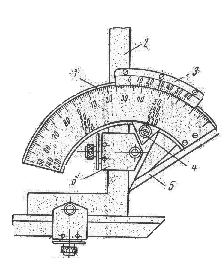 Fig. 18. Universal Angle Gauge: Fig. 18. Universal Angle Gauge:1— base; 2 — triangle; 3 — vernier; 4 — quadrant; 5 - detachable rule; 6 - holder ___________________ 1. they are graduated in thirty-seconds and sixty-fourths of an inch — они градуируются в тридцать вторых или шестьдесят четвертых дюйма Exercises I. Use the following words and phrases in sentences of your own: drawing, to measure, to involve, mating part, accuracy, slide gauges, vernier calipers, depth gauges, clearance gauges, inside calipers, outside calipers, to graduate, internal diameters, to slide, adjusting screws, lock nut, tapped hole. II. Translate the following groups of words, paying attention to the meaning of suffixes: to measure, measuring, measurable, measured, measurement; to compare comparative, compared, comparison; to signify, significant, significance; to depend, depending, dependence, dependent; to graduate, graduated, graduation; accuracy, accurate; precise, precision; general, generally,generation. III. Supply synonyms for the following words: to place, inside, outside, to be similar, according to, with reference to IV. Fill in the blanks with prepositions in accordance with,by means of, within, for, to, of: 1. Machine parts should be manufactured ... their respective drawing. 2. ... a micrometer it is possible to make measurements to a very high degree of accuracy. 3. Calipers are used for measurements to ... 0.18 mm. 4. Measuring tools should be chosen ... the machine part to be measured. 5. The micrometer is an instrument ... measuring directly ... thousandths, and estimating to quarter thousandths ... an inch, ... its range. V. Translate the following sentences observing different meanings of me. words in italics: 1. The principle involved in the operation of the micrometer is explained in technical text-books. 2. The instruction on the use of this dial indicator is rather involved. 3.These drawings and their explanations are given to illustrate the principles involved. 4. Different kinds of instruments are used to measure holes of considerable depth. 5. A millimetre is a measure of length. 6. Steel plates usually vary by sixteenths of an inch. 7. By dividing the load required to break the specimen by its area, the ultimate tensile strength of material is obtained. 8. By accuracy of form is meant not only the exact duplication of irregular profiles, but also the accuracy of form embodied in squares, true cylinders, cones, etc. VII. (a) Translate the following text using a dictionary: A range of optical instruments for measuring surface finish, which are relatively inexpensive and of very robust design, and afford the advantage that they can readily be applied under both workshop and inspection-room conditions, is being produced by many plants. Known as optical devices, these units are of modern designs. The portable device is intended for checking the relatively coarse finishes produced by planning, turning, and milling. With this device a beam of light is directed past a straight, opaque edge, and through a lens at an angle of 45° to the work surface, and the line of intersection is observed at an angle of 90 to the light beam, through the eyepiece of the microscope. (b) Make up three questions on the basis of this text and answer, them. VIII. Make up questions concerning the measuring tools shown in Figs 11, 12 and answer them. IX. Using the following words and word combinations describe the principle of operation of the vernier calipers shown in Fig. 13: vernier calipers, to be used, to measure, external and internal sizes, a part, to consist of, steel scale, four jaws, two jaws, to be attached, the frame, to slide, the scale, the first two jaws, to be used, measuring external surfaces, the other two jaws, measuring internal surfaces, the depth, to be measured, a spindle X. Giving answers to the following questions describe the principle of operation of the micrometer shown in Fig: 14: 1. What is a micrometer? 2. What is the function of the graduated thimble of the micrometer? 3. What; is the scale on the micrometer barrel used for? 4. Where is the part placed for measurement? 5. How is the part pressed to the anvil and how is the micrometer reading taken? XI Describe the measuring tools shown in Figs 15, 16, and 18. 6. MACHINE-CUTTING TOOLS The cutting tool is that part of a cutting machine which serves for removing material from revolving work. If either incorrect or faulty cutting tools had been used for metal-cutting operations, the quality of work would have become poor and cost would have been higher. That is why careful attention should be given to the cutting tools in any metal-cutting operation. Cutting tools are made of hardened and tempered steel r or alloy metals. All the cutting tools are adapted to perform certain work in the most efficient manner and, accordingly, they may be subdivided into turning tools, boring tools, milling cutters, planing tools, shaper tools, etc. These tools having one effective cutting edge along which excess material from the workpiece is removed are known as single-pointcutting tools. Other tools removing excess material on two or more cutting edges simultaneously are known as multiple-point faulting tools. Each cutting tool consists of a shank for holdingthe tool in the machine and a tip or cutting edge for removing chips from the work. The single-point cutting tools fall into several types, such as: solid, forged tools having the same material throughout; (2) solid tools having a tough steel shank and а tiр made of high alloy steel which is welded on to the shank; (3) solid tools with a tip brazed (Fig. 19) on to the shank; and (4), inserted tools having a small piece of the cutting edge made of carbide steels. Inserted tools held in a tool holder owing to a screw wedge are used for machines of a complicated nature when it is necessary to prolong tool life as long a time as possible. 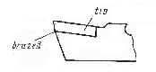 Fig. 19. Cutting Too Fig. 19. Cutting TooThe various types of cutting tools differ in shapes, and in the angles to which: the surfaces of the tools are ground. The cutting tip should be ground by hand or by machine withcorrect angles (Fig. 20) on the top face (rake angles) and sides (clearance angles) to a desired shape. The shape of the tool, as well as the proper rake and clearance angles depend upon a large number of factors, such as the specific operation, the material to be cut and the material from which the tool, is made. The top rake is usually provided for the tool holder by the tool being set at an angle, which is correct for machining steel and cast-iron. On solid tools it is necessary to grind the top rake in the tool. By adjusting the tool in the tool post through a wedge, this top rake can be varied somewhat to suit the material being turned. The softer the material the less the top rake should be as there is a tendency for the tool to dig in if the rake is too great. The side rаке also varies with material being machined. The proper angle is 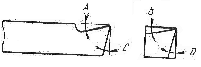 Fig. 20. Cutting Tip: Fig. 20. Cutting Tip:A - top rake; B - side rake; C - front clearance; D - side clearance from 6° for soft material to 150 for steel. The front clearance depends: on the diameter of the work to be turned. To turn cast-iron it is advisable to set the tool above; centre. If the tool were ground square1 without any front clearance, it would not cut but rub on the material to be turned below the cutting edge of the tool. The front clearance should be less for small diameters than for large diameters, ranging, from 8 to 15°. The tool is ground with, the side clearance to prevent the dragging of the tool on the shoulder formed by the cut. This angle is usually about 6° from the vertical and is constant. For efficient operation of the machine, the proper surface speed of the work being machined must be maintained. If the speed is too slow, the job takes more time than necessary and often the work produced is unsatisfactory. On the other hand, if the speed is too great, the cutting edge will be worn down too rapidly. Frequent grinding will be necessary, which is also wasteful. For ordinary production work the speed should be as great as the tool will stand without requiring sharpening more often than every: two or three hours when cutting continuously. Cutting tools used for longitudinal turning are subdivided into toughing tools and finishing tools. Roughing tools are applied for roughing or removing the excessive metal from the work. Such tools are usually carbide-tipped and they have a long cutting edge. Angular roughing tools are very convenient for turning surfaces of the parts which are at the chuck cams, as well as for facing. Finishing tools are used after the work has been turned with a roughing tool to give accurate size and clean surface to the work being machined. Before starting the cutting operation tools should be clamped in the tool-holder (Fig.; 21) by means: of two or more bolts. Side tools are used for cutting faces. A side tool has a long cutting edge set at an angle of about 5° with respect to the surface of the work to be cut, and a short cutting edge. This cutting edge, is largely bevelled to facilitate the approach of the tool tip to the centre of the part fastened between the two lathe centres. Necking tools are used for grooving, since the width of grooves is usually small. The cutting edge of a necking tool is narrow, which increases the danger of its breakage. To prevent this breakage the height of the head is made several times larger than the width of the cutting edge. Material is cut off by means of tools known as cutting-off tools, which are similar to necking tools. The difference is that they have a longer head which should be a little larger than one-half of the diameter of the blank to be cut. ___________________ 1. If the tool were ground square — если бы резец затачивался под прямым углом 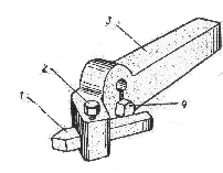 Fig. 21. Tool Holder Fig. 21. Tool Holder1— cutting tool; 2 — bolt; 3 — shank; 4 — bolt |