|
|
курсач. готовый диплом 2. Федеральное государственное бюджетное образовательное учреждение высшего образования морской государственный университет
6.2 Controller Features
The governor features include:
State-of-the-art speed sensing and control algorithms
Built-in user interface which provides speed raise/lower functions
Speed Control with Droop and Dynamics features
Configurable speed settings and adjustment rates
Multiple Fuel Limiting algorithms, such as jump-rate, boost pressure, and
start fuel limiting
Temperature monitoring
Run / Stop
Status discrete output
Speed setpoint adjustments using a 4-20 mA analog input or raise/lower
discrete inputs or front panel raise/lower commands
Front panel Droop, Stability, and Load Limit adjustments are also available
Comprehensive diagnostics for easy troubleshooting
6.3 Description and principle of operation of the UG-40 regulator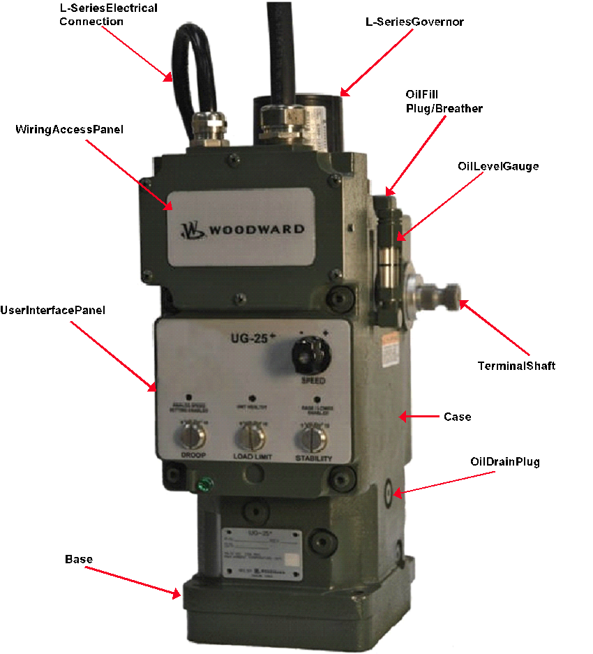
Figure 6.1 UG25+ Governor Overview
6.4 Description of Operation
6.4.1 General
The UG-25+ governor is a digital speed control with integral speed and position
feedback. The governor output shaft provides a maximum rotation is 42 degrees for
controling diesel, gas, or dual fuel engines, or steam turbines. The speed setpoint can
be adjusted with a 4-20 mA analog input or with raise/lower discrete inputs.
The UG-25+ front panel provides a convenient operating interface for the user.
These functions and adjustments include:
STOP The Stop button is not needed for turbine applications.
SPEED Selecting the (+) and (-) direction causes the speed setting to be
raised or lowered. The speed setting will move toward the speed setting’s upper
or lower limit at the raise and lower speed setting rates for as long as the spring-
loaded, return-to-center, selector switch is manually held in the (+) or (-)
direction, Releasing this switch causes the speed setpoint to remain at that
setting. Speed adjustment commands from this front panel switch have priority
over external raise and lower commands. When raise and lower commands,
come from the front panel, remote raise and lower commands are ignored. This
switch and external raise and lower commands are not active and will not change
the speed setpoint when the external Analog (4 to 20 mA) speed setting signal is
enabled.
ANALOG SPEED SETTING ENABLED LED — This LED illuminates when
the external Analog (4 to 20 mA) speed setting signal is enabled. The speed setpoint
can be moved with the external Analog (4 to 20 mA) speed setting signal
between Min Speed Limit (4 mA) and Max Speed Limit (20 mA). The manual
front panel SPEED switch and the external raise and lower contact inputs are not
active when this LED is on.
UNIT HEALTHY LED — This LED illuminates when there is electrical power
supplied to the UG-25+ and the L-Series electronic governor internal to the
UG-25+ is working properly. This LED goes off if supply power is removed or
there is a fault in the L-Series electronics. See the "Shutdown Faults and Stop
Details" section later in this chapter.
RAISE / LOWER ENABLED LED - This LED illuminates when either the
manual front panel SPEED switch or the external raise and lower contact inputs are
available to change the speed setpoint. This LED goes off the external Analog
(4 to 20 mA) speed setting signal is enabled.
DROOP Adjustment — This adjustment allows the amount of output position
droop (as a function of terminal shaft position) to be set between zero and to
about ten percent (assuming 30 degrees of terminal shaft travel). Setting the
adjustment fully CCW (counterclockwise) sets zero droop into the governor for isochronous operation
Load LIMIT Adjustment This adjustment limits the rotational travel of the output
terminal shaft, which in tur, limits the fuel going to the engine and, therefore, the
amount of load the engine can carry. The position limit setting is linear from 0% at
full CCW to 100% at full CW. The use of the LOAD LIMIT. Adjustment must be
configured when the governor is configured and the external Boost Input Selector
discrete input must be open (disabled).
STABILITY Adjustment This adjustment allows quick access to the governor's
dynamic performance adjustments: P (proportional) and I (Integral) gain terms.
The adjustment ranges from 0.5 (fully CCW) and 2.0 (fully CW) times the nominal
gain settings. A multiplication factor of one is applied to the gain settings when
the adjustment is set to mid position (12 o'clock)
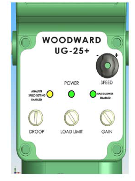
Figure 6.2 UG25+ Front panel overview
Control adjustments are made from a PC using the UG-25+ Service Tool. The
Service Tool is a Windows-based software tool used to configure, monitor,
adjust, and troubleshoot a UG-25+ governor. It runs on a personal computer and
communicates with the UG-25+ governor through an RS-232 serial connection.
The UG-25+ Service Tool includes optional password protection to provide
securily against tampering.
The internal speed sensor input contains a filter that minimizes the effects of
firing torsional that occur normally in reciprocating engines. This filter ensures
the governor will not react to speed sensor input changes produced by firing
torsionals. This provides exceptionally smooth steady-state speed control and
allows matching the control dynamics solely to the engine rather than detuning
dynamics to compensate for firing torsional frequencies.
The control has a switching power supply with excellent spike, ripple, and EMI
(electromagnetic interference) rejection. Discrete inputs are capable of rejecting
EMI and variable resistance in switch or relay contacts. Analog inputs are
differential type with extra filtering for common-mode noise rejection.
The control provides one discrete output, which provides a Unit Healthy
Indication
6.5 Principal of Operation
The UG-25+ consists of the following 3 main components:
Controls prime mover speed/load with proportional rotary output by using
speed reference/customer inputs.
Amplifies work output of L-Series governor.
Provides local control of droop, load limiting, stability and shutdown
functions. Also provides electrical connector for power and customer inputs.
The hydraulic amplifier operation is depicted, which illustrates the working relationship of the various parts. The main elements of the hydraulic, amplifier are listed below:
Gear rotor pump configuration. Pump is driven by the governor drive-shaft to provide at pressure for the governor. The pump is fed all from the self-contained sump.
Relief Valve
Set to maintain internal operating pressure at 1034 kPa (150 psi)
Rotary to Linear Conversion Mechanism
This mechanism converts rotary to linear motion to operate the pilot valve. It also
provides enough linear motion to convert 50 degrees of L-Series travel to 42
degrees of terminal shaft rotation when coupled to the rest of the linkage in the
hydraulic amplifier.
Return Spring
Used to provide shutdown to minimum fuel position upon loss of function of the
L-Series.
Pilot Valve Plunger
The 3-way pilot valve directs flow to the control side of the differential area power
piston or to governor drain
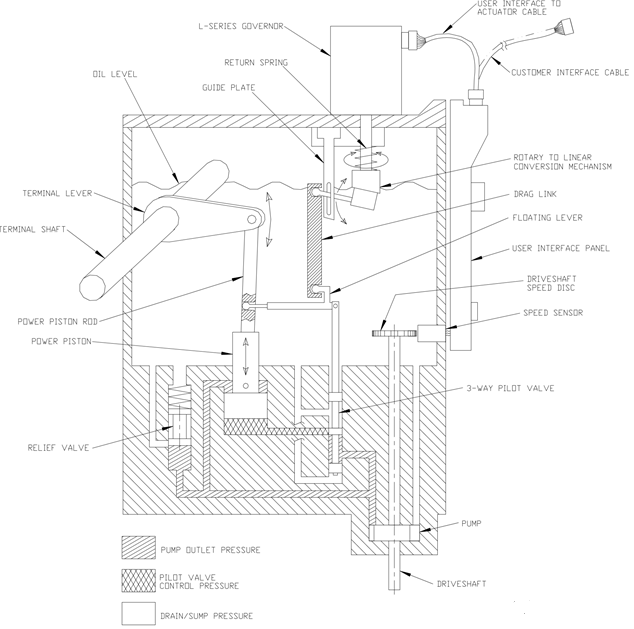
Figure 6.3 Governor functional Overview
6.5.1 Power piston, Terminal level and Terminal shaft.
The terminal lever converts the linear motion of the differential-type servo piston
to rotary motion of the terminal shaft, which in turn moves the fuel linkage. The
terminal-shaft position is fed back to the torque-motor beam to provide the
proportional control.
Speed Sensing Disk and Speed Sensor
Drive-shaft-driven 20-tooth gear with proximity probe speed sensor used to
Provide a speed signal to the L-Series governor
Increase in Load or Speed Setting
An increase in load, or speed setting, causes the L-Series governor output shaft
to rotate CCW when viewed from the top on the UG-25+. This, in tur, causes the
pilot valve to lift allowing control pressure to act on the underside of the power
piston. This pressure underneath the power piston opposes the pump outlet
pressure acting on the topside and causes the piston to rise, since the piston
bottom has twice the area of the topside.
As the power piston rises, the power piston rod moves with it and rotates the
terminal shaft, converting the output motion back to rotary. One end of the
floating lever is directly connected to the power piston rod and this end rises.
When the desired terminal shaft position is reached due to the correct speed or
load setting being achieved, the floating lever provides a mechanical
feedback/restoring signal between the power piston rod and the pilot valve.
During this condition, the pilot valve will be a its “null” position. Therefore, the
L-Series governor and the hydraulic amplifier are proportional devices with their
positions a direct function of the load or speed setting.
Decrease in Load or Speed Setting
A decrease in load, or speed setting, causes the L-Series governor output shaft to
rotate CW. This, in turn, causes the pilot valve to lower allowing the control pressure
acting on the underside of the power piston to flow to drain. The pump outlet
pressure acting on the topside ofthe power piston will cause the piston to lower.
As the power piston lowers, the power piston rod moves with it and rotates the
terminal shaft towards the minimum fuel direction. The floating lever then lowers
its end coupled to the power piston rod and provides its position feedback/restoring
feedback to the power piston and pilot valve.
Loss of Control Voltage
Upon loss of control voltage, the governor terminal shaft goes to minimal fuel,
thus offering a safety feature. With loss of control voltage, the L-Series governor
loses torque and the force of the loading or return spring causes the center
adjustment to lower. The pilot valve follows, keeping the control port uncovered.
Trapped oil escapes to drain, and the servo power piston moves down until it
reaches minimum fuel position.
6.6 Speed Governor Features Description
The user must set up the speed input, speed setpoint/rates, start setting and
fuel limit. The user can set multiple dynamics as necessary for stable operation.
The user can choose all or none of the security functions depending on the
application,
The governor features include:
Speed Control with Droop and Dynamics features
Fuel/Load Limiter (both startup and run time)
Jump & Rate Limiter
Temperature monitoring
Run / Stop
Status discrete output
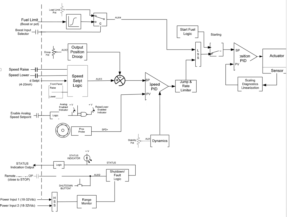 Figure 6.3 Governor Function Overview Figure 6.3 Governor Function Overview
6.6 Speed Control Functions
Speed Input
Internally, the UG-25+ governor houses a proximity probe mounted next to a
20-tooth gear, which provides a speed signal to the control. Digital speed
detection with firing torsional fitering is used for detecting engine speed. This
digital detection method senses speed very quickly for rapid response to speed
changes, The input frequency is converted to engine speed based on the number
of gear teeth, gear ratio, number of cylinders, and engine stroke settings
configured.
Speed Setting Options
The speed control setpoint is abjustable with rise or lower commands through
the user interface on the UG-25+ front panel or from remote contact inputs. In
addition, a 4-20 mA analog input provides for remote speed setpoint control.
The speed setpoint can be in Analog or raise/lower mode. The front panel LEDs
will display the active speed setpoint mode (Analog or raise/lower). When in the
Analog mode, the setpoint signal comes from the UG-25+ analog speed setpoint
input (derived externally by a customer supplied device). When in the raise/lower
mode, the setpoint is adjusted using raise and lower commands available both
on the front panel and through customer inputs.
Analog Speed Setpoint
The Analog Speed Setpoint input directly sets the internal speed setpoint. The maximum rate at which the analog input signal can change the speed setpoint is programmable and provides separate increase and decrease rate limits. The analog setpoint is enabled with the Enable Analog speed setpoint discrete input. The analog setpoint scaling is based on the Min Speed Limit and Max Speed Limit settings, a 4 mA input corresponds to Min and a 20 mA input corresponds to Max.
Analog speed setting mode is active only when the Analog Enable input is
closed and the analog input signal is above 2.5 mA. All Setpoint Raise/Lower
commands are ignored when the Analog Speed Setting mode is active.
The user must provide an external means to clamp the analog speed setpoint
input between 3 and 21 mA. An analog speed setpoint command input below 3
mA or above 21 mA is out of the normal 4 to 20 mA input range and may cause
the analog speed setpoint command function to become disabled even though
the Analog indication LED remains on.
When the Analog Speed Setpoint mode is disabled, by loss of input signal or
opening the Analog Enable input, the speed control's setpoint is held at the last
setting and remains there until adjusted using the Raise or Lower commands.
Lower. The Lower Speed discrete input and front panel Lower command act
directly on the internal speed setpoint and will progressively decrease the speed
setpoint down to a programmable lower limit at the programmed lower rate for as
long as the input is selected (closed). When this input is not selected (opened),
the speed reference will remain fixed at the last setting.
Raise. The Raise Speed discrete input and front panel Raise command act
directly upon the internal speed setpoint and will progressively increase the
speed reference up to a programmable upper limit at the programmed raise rate
for as long as the input is selected (closed). When this input is not selected
(opened), the speed reference will remain at the last setting.
Front panel commands have priority over external commands — when Raise or
Lower is selected locally, the remote raise/lower commands are ignored. In the
event of a simultaneous external Raise and Lower command, the Lower has
priority over a raise command.
Speed Control Dynamics
The control algorithms used in the UG-25+ governor are designed specifically for
reciprocating engine applications. The UG-25+ offers either a single set of
dynamics or a position-based curve. In addition, cold start dynamics and dual
gain settings can be configured for use in more demanding applications. These
options are described below. A front-panel Stability potentiometer is provided to
allow quick access to dynamic performance adjustments.
Cold Start Gain
In demanding gen-set applications that require ISO 8528-5, Class G3.
performance but are also intolerant of cold start instability, the UG-25+ governor
offers a cold start gain function that sets the gain of the controller to a lower-than-
normal value until a programmable speed threshold is This gives an turbine
time to warm up slightly before switching to a normal gain value.
Single Gain
If configured for Single Gain, once the Start Gain Speed Threshold is exceeded,
the proportional gain remains constant as entered and does not vary with engine
speed or load. These are simplest dynamics and suit most constant speed
applications. A single gain setting is typically used on turbines that operate
continuously at rated speed or on variable speed turbines that tend to be stable
at all speeds with constant dynamic settings.
Position Curve
A Position Curve varies the proportional gain value with fuel demand (governor
position). Fuel demand is roughly proportional to load but not necessarily in a
linear manner. A 5-breakpoint gain curve is provided to map gain versus fuel
demand. Gain is applied linearly between breakpoints. This gain curve is
particularly useful for non-linear fuel systems (e.g., intake butterfly valves).
Integral and Derivative
The integral gain varies with engine speed. Idle Integral applies when running at
the initial Run Speed. Rated Integral applies when operating at rated speed or
higher. The gain varies linearly at intermediate speeds. For all dynamic
configurations, the Derivative setting is constant and does not vary with either
engine speed or load.
Stability Pot
The front panel stability pot provides a quick adjustment on the speed controller
P (proportional) and I (integral) gain terms. This pot output, with a range of 0.5 to
2 X, is multiplied with the nominal gain settings to adjust the resultant
performance. When the pot is at mid position, the multiplier is “1.0° and gains are
at their nominal configured settings. At full clockwise position, P and I-term gains
at multiplied by ‘2’ providing increased response and at full counter-clockwise
position the multiplier is at 0.5. The stability pot input and resultant gains can be
monitored from the Overview tab on the Service Tool.
Dual Gain Settings
Gain Window and Gain Ratio settings further modify the applied gain. These Dual
Gain Dynamic settings can improve both steady state and transient load
performance by automatically switching between two gain settings. A low gain
setting is applied during steady-state operation. A high gain setting is applied
during load transients. Dual Gain Dynamics are available for all gain
configurations.
During steady-state loaded operation, the control uses the primary gain setting
(rated gain, idle /rated gain, etc.). In this region, gain is set to prevent the control
from responding to minor speed fluctuations inherent with reciprocating engines.
This essentially eliminates harmful jiggle of the governor output and the fuel
system linkage during steady-state loaded operation.
During load transients, should the speed error exceed the adjustable Gain
Window width, the primary gain setting is multiplied by the gain ratio seting to
temporarily increase the applied gain. This higher gain produces a faster fuel
response to quickly restore engine speed to the speed setting. Speed error is the
difference between actual engine speed and the engine speed setting, The
primary gain setting is restored once the control senses a return to steady-state
operation. Setting the gain ration to 1 disables the function.
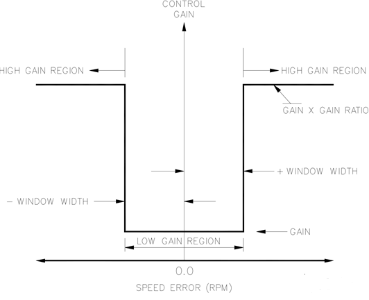
Figure 6.4 Dual Gain Settings
Control Modes
The Service Tool displays the state of the UG-25+ governor, the present mode of
the unit. Options include:
Stopping
Engine Stopped
Power-down
Start Fuel 1
Start Fuel 2
Ramping
Running Rated
Stopping
The stopping state indicates the control has a shutdown fault and is driving the
output shaft position to the closed position. Once speed has reached zero rpm,
the control transfers to the stopped state.
Turbine Stopped
In this state the engine is stopped and the control is ready to begin the startup
cycle if there are no shutdown's active. After the Stopped State Delay, the
holding current is applied to the governor to limit the current draw and prevent
battery drain.
Power down
In this state the governor position controller is turned off and the holding current
is applied to the governor to limit the current. This state is only used if the engine
is stopped and the run enable discrete input is not active.
6.7 PID Tuning
The UG-25+ is configured using the Service Tool, refer for Service
Tool installation and connection instructions. This chapter covers the process of
tuning and servicing the control via the UG-25+ Service Tool. It is assumed that
the control has already been installed on the engine.
An application requires the following setup steps. In many applications these
steps have already been performed by the OEM.
In addition, jump and rate limit settings and the position controller proportional
gain term can be adjusted to meet application requirements.
The Service Tool can be used to tune the Speed PID or to just trend/monitor the speed PID output. The Speed PID Dynamics screen is opened by selecting ‘Edit Speed Dynamics’ under the ‘Tools’ menu.
properties including the speed
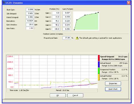
Figure 6.5 Service Tool – Speed Dynamics Position Curve
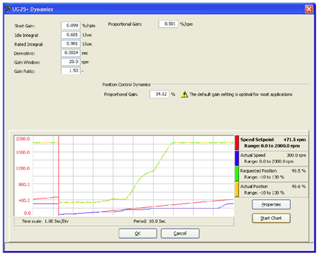
Figure 6.6 Service Tool – Speed Dynamics Single Gain
6.8 Adjusting Trend Settings
Pressing the Properties button pops open the Properties Window.
From this window the user can adjust the trending window properties including
the update rate and display range.
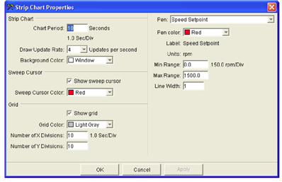
Figure 6.7 Service Tool
PID Tuning Properties Window
Each trend line, called pens, can be individually modified from the Properties
window. To change the properties of a trend, select the pen from the drop-down
Window: The color, range, and line width of each pen can be modified.
6.9 Speed PID Dynamic Settings
The Speed loop utilizes a PID controller. The response of this control loop can be
adjusted for optimum response, however itis important to understand what a PID
controller is and the effect each controller adjustment has on the controller
response. Proportional gain (P), integral gain (), and derivative (D) are the
adjustable and interacting parameters used to match the response of the control
loop with the response of the system.
6.9.1 Proportional Control
Proportional response is directly proportional to a process change.
Analogy: Setting the throttle on an automobile to keep constant speed on a
straight and level road.
Proportional control (using the same analogy) results in a certain speed as long
as the automobile is not subjected to any load change such as a hill. fa throttle
is set to any particular setting, the speed of the automobile will remain constant
as long as the automobile remains on a straight and level road. If the automobile
goes up a hil, it wll slow down. Of course, going down a hill the automobile
would gain speed.
6.9.2 Integral Control
Integral compensates for process and setpoint load changes.
Analogy: An automobile’s cruise control maintains the automobile’s constant
speed regardless of hills.
Integral, sometimes called reset, provides additional action to the original proportional response as long as the process variable remains away from the setpoint. Integral is 2 function of the magnitude and duration of the deviation. In this analogy the reset response would keep the automobile's speed constant regardless of the terrain.
6.9.3 Derivative
Derivative provides a temporary over-correction to compensate for long transfer
lags and reduce stabilization time on process upsets (momentary disturbances).
Analogy: Accelerating an automobile into the high speed lane with merging
traffic.
Derivative, sometimes called “preact” or ‘rate’, is very difficult to draw an
accurate analogy to, because the action takes place only when the process
changes and is directly related to the speed at which the process changes.
Merging into high speed traffic on a highway from an “on’ ramp is no easy task
and requires accelerated correction (temporary overcorrection) in both increasing
and decreasing directions. The application of brakes to fall behind the automobile
inthe first continuous lane or passing gear to get ahead of the automobile in the
first continuously lane is derivative action.
6.9.4 Proportional Response
The amount of controller change is directly related to the process change and the
Proportional gain setting on the controller; Controller output change is
Proportional to the process change. If there is no process change, there is no
change in output from the controller (or valve change) regardless of the
deviation. This results in an undesired offset between the original desired
Setpoint and the resulting drop in the Control Point.
Starting at the top of the graph a load change is introduced, With a small Proportional
gainb (meaning a large process change is required to produce full valve travel),
stability is good but offset is very high. With a moderate gain setting (higher number
setting) stabilty is still good offset is still faly high. With a high setting, offset is,
considerably smaller but the stability is poor. The 0.25 ratio effects a minimum
area whereby the offset is reduced to a minimum while stability is in a decaying
manner at 0.25% ratio. The decay ratio used (0.25%) means that if the second
cycle is 1/4 of the first cycle, then each succeeding cycle will be 1/4 of the
preceding cycle until the cycle is not visible.
Since Proportional gain is adjusted to produce (only) the proper stability of a
process, do not continue increasing its effect to correct offset conditions. The
amount of stability and offset is directly related to the setting of the Proportional
setting, Stability is of course also affected by the stability of the process. In
essence, the amount of output from the controller due to the Proportional setting
is from the error. If there is no error, then there is no Proportional effect.
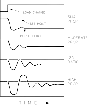
Figure 6.8 Proportional Gain Setting Effects
6.10 Integral Response
In the UG-25+, integral gain is in unis of repeats per second (or Reset Rate).
Therefore, a high amount of Integral gain (high number) would result in a large
amount of Reset action. Conversely, a low Integral gain (low number) would
result in a slower reset action.
Integral response is provided to eliminate the offset that resulted from straight
Proportional control. «Integral response» shows how the controller action is
Proportional to the measurement change, but this results in offset. The Integral (or
Reset) action is a function of both time and magnitude of the deviation. As long as
an offset condition (due to load changes) exists, Integral action is taking place.
The amount of Integral action is a function of four things:
1. The magnitude of the deviation.
2. The duration of the deviation.
3. The Proportional gain setting.
4. The integral setting.
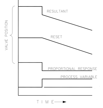
Figure 6.9 Open Loop Proportional and Integral Response
In this Open Loop figure the Integral response is shown increasing due to the offset
condition existing between the process variable (like speed) and the setpoint. The
resultant action is the top curve showing the step Proportional response that ends as
soon as the measurement stops changing, Then the Integral (or reset) action is added
to the Proportional action in an amount equal to the Integral of the deviation. In other
words, Reset action continues (in either or both directions) as long as there is a
difference (deviation) between the setpoint and the process measurement. In this
case, the deviation will never be eliminated (or even reduced) because the system
is in Open Loop.
Shows the closed loop effects of integral action. The bottom curve displays the load
change. The next curve up shows the setpoint and the measured process variable.
With the load change, the process variable (like speed) droops or deviates from the
setpoint. The next highest curve is the Proportional action and follows the measured
variable proportionately. The Integral curve adds to the Proportional curve resulting
in a different output position, thereby returning the process to the Setpoint.
In Closed Loop, however (as opposed to Open Loop), as the measurement
decays toward the Setpoint the Proportional action is taking place Proportionally
to the measurement change, and the Integral action is decaying proportionately
to the magnitude and duration of the deviation until the measurement reaches
the setpoint at which time the Integral action is zero.
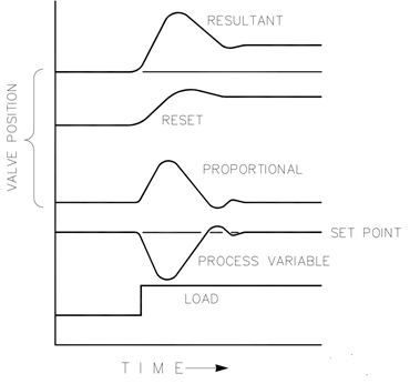
Figure 6.10 Closed loop proportional and integral response
Shows the effect of fast or slow Integral action. For a given load change an offset
results with Proportional response only. Since recovery time (for a given load
change) is important, the Integral setting should remove the offset in a minimum
time without adding additional cycling. Ideally, the process should not continue to
cycle after the setpoint has been reached as in the second curve from the bottom.
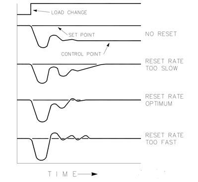
Figure 6.11 Integral Gain (Reset) Setting Responses
6.11 Derivative Response
In a process control loop the Derivative action is directly related to how fast the
process changes (rate of change). If the process change is slow then the
Derivative action is proportional to that rate of change. Derivative acts by
advancing the Proportional action. Derivative acts at the start of the process
change, when the process changes its rate and when the process stops its
change.
Derivative action takes place at only three times:
1, When the process starts to change.
2. When the rate of change takes place in the process.
3. When the process stops changing.
The net result of Derivative action is to oppose any process change and
combined with Proportional action to reduce stabilization time in returning the
process to the setpoint after an upset. Derivative will not remove offset.
Shows how Derivative acts to oppose a change in process in either direction. The dashed line shows the Derivative action going through zero to oppose the process deviation traveling toward zero, Notice offset still exists between the desired setpoint and the drooped control point that resulted from the load change. The top curve is the resultant controller output, Proportional plus Derivative. If an upset (momentary) had occurred rather than a load change, there would be no offset.
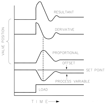
Figure 6.12 Closed loop proportional and derivative action
Show the effect of different Derivative settings. The curves are relative since it depends on what type of control is desired in order to properly adjust Derivative time. In all the above curves, the offset still exists since offset, can only be eliminated by the addition of Integral (or Reset).
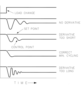
Figure 6.13 Derivative Setting Effects
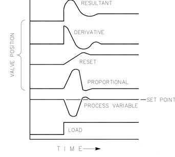 Figure 6.14 Closed Loop Proportional, Integral and Derivative Action Figure 6.14 Closed Loop Proportional, Integral and Derivative Action
Show the relationship of output position to the interaction of the PID modes of
control whenever a load change takes place in closed loop. As the process variable
drops due to the load change, the proportional action moves the control valve
proportionately to the measurement (process variable) change. The integral
gain/reset adds to the proportional action as a result of the magnitude and time
(duration) of the deviation. And the derivative temporarily over-corrects based on
the speed at which the measurement moves in any direction. The resultant curve (at
the top) shows a similar over-correction (in this case), but in addition the valve will
stay at the new position required to keep the measurement at the setpoint.
Derivative provides a temporary over-correction to compensate for long transfer
lags and reduce stabilization time on process upsets (momentary disturbances).
Another possible use of the derivative adjustment is to reconfigure the controller
From a PID to a controller. This is done by adjusting the derivative term to zero.
6.12 General Field Tuning Guidelines
Best results are obtained when the adjustment (tuning) is done systematically.
Prior training and experience in controller tuning are desirable for effective
application of this procedure. The settings made for one operating set of
conditions may result in excessive cycling or highly damped response at some
other operating condition. The tuning procedure should be applied under the
most difficult operating conditions to assure conservative settings over the
normal operating range. The UG-25+ can be configured for a 5-point position
curve, providing greater flexibility in dynamics settings over this range.
Itis good practice to keep the average of the setpoint changes near the normal
setpoint of the process to avoid excessive departure from normal operating level
After each setpoint change, allow sufficient time to observe the effect of the last
adjustment. Itis wise to wait until approximately 90% of the change has been
completed.
Another item to keep in mind is that the stability and load limit functions are
physically disconnected when the service tool harness is installed (Service Tool Homes Connection). The ability to replicate (simulate) these inputs is provided on the Simulated IO tab.
To provide the same dynamic performance settings, the gain value of the front
panel stability pot must be replicated/simulated in software. This can be done
either by moving the stability pot back to mid (multiplier of 1’) or by setting the
service tool multiplier to match the pot value. Note that the stability pot provides a
multiplier on the gain (P) and integral I) settings. When the pot is at mic-position,
the multiplier is 1” and the gains will be at their nominal configured values. The multiplier is ‘0.5' when the pot is fully CCW and '2.0' in the full CW position.
6.13 If System is Unstable
If the system is unstable, make sure the speed PID dynamics is the cause. This
can be checked by reducing the load limiter until it has control of the governor output. If the governor is causing the oscillation, time the oscillation cycle time. A rule-of-thumb is, if the system’s oscillation cycle time is less than 1 second reduce the Proportional gain term. A rule-of-thumb is, if the system's oscillation cycle time is greater the 1 second reduce the Integral gain term (proportional gain may need to be increased also).
On an initial startup with the UG-25+ all PID dynamic gain terms will require
adjustment to match the PID response to that of the control loop.
The proportional gain setting of the position controller is also available for
adjustment on the dynamics tuning window. Reducing this gain will lower the overall control bandwidth. Lowering this gain term in some systems can reduce the nervousness of the output shaft. The nominal gains settings are optimal for most applications but if the speed controller dynamic adjustments do not achieve the desired result, modifying this setting my help.
7 Ремонт вала поршневого насоса
7.1 Техническая характеристика объекта
Назначение и характеристика конструкции
В данном дипломном проекте рассматривается ремонт вала поршневого насоса фирмы HAWE Hydraulik V30E [1]. Так как взяли за основу насос иностранного производства, то мы взяли за основу материал который является аналогом насоса V30E. Аналогичным материалом для изготовления вала поршневого насоса V30E, — сталь 40Х ГОСТ 4543-2016[2] в результате износа, старения и деформации нарушаются размеры поверхностей. Как итог износ шпоночного паза. В процессе восстановления наряду с доведением размеров поверхностей и шероховатостей до номинальных значений необходимо восстанавливать и их форму.
Таблица 7.1 - Основные параметры вала насоса
Параметр
|
Значение
|
Наибольший диаметр вала, мм
|
51
|
Длина вала, мм
|
614
|
Масса вала, кг
|
12,6
|
Материал
|
Сталь 40Х ГОСТ 4543-2016
|
Материал
|
Предел текучести
|
Сопрот. разрыва
|
Ударная вязкость
|
Твердость
|
Стандарт
|
Сталь 40Х
|
785
МПа
|
980
МПа
|
59
кДж/м
|
217
HВ
|
ГОСТ
4543-2016
|
Таблица 7.2 - Краткая характеристика стали, из которой изготовлен вал насоса Сталь 40X ГОСТ 4543-2016 [2]
Гладкие валы и оси составляют большую часть номенклатуры восстанавливаемых деталей. В большинстве случаев именно эти детали лимитируют ресурс узлов и агрегатов машин. Коэффициент их восстановления при капитальном ремонте машин составляет 0,25-0,95.
Длина восстанавливаемых валов составляет от 100 до 4000 мм. Диаметры валов равны 12-210 мм, но у 98 % валов диаметр не превышает 60 мм. Масса валов 0,2-50 кг (среднее значение около 3 кг). [3]
Таблица 7.3 – Марки и химический состав материалов
Деталь
|
Материал, ГОСТ
|
Химический состав
|
Вал насоса
|
Сталь 40X
ГОСТ 4543-2016
|
С = 0,36÷0,44 %
Mn =0,5÷0,8 %
Si = 0,17÷0,37 %
Cr = 0,8÷1,1 %
| |
|
|
 Скачать 3.93 Mb.