AГЛИЙСКИЙ. Пособие по английскому языку для машиностроительных вузов допущено Министерством высшего и среднего
 Скачать 1.36 Mb. Скачать 1.36 Mb.
|

|
CHAPTER IV METAL-CUTTING MACHINES 1. LATHES A lathe is known to be essentially a machine tool for producing and finishing surfaces of workpieces. The machine is designed to Hold and revolve work Ground an axis of rotation so that it may be subjected to the action of a cutting tool moving in a horizontal plane through, the axis of the work. When the, cutting tool moves in a longitudinal direction or parallel to the axis, the operation is known as "turning"; when it moves in a transverse direction, it is known as "facing". In addition to turning and boring, which the machine is primarily designed for, many other operations, such as drilling, threading, tapping, and by employing special adapters grinding and milling, may be performed on a lathe. Lathes used in shop practice are known to be of different designs and sizes. These lathes fall into various types, either according to their characteristic constructional features, or according to the work for which they are designed. The size of a lathe is determined by the diameter and length of work that may be swung between centres. Lathes of comparatively small size, which may be mounted on a bench, are termed bench lathes, and are intended for small work of considerable accuracy; lathes provided with tools held in a revolvable turret are called "turret lathes": lathes in which workpieces to be treated are held in a chuck are known as "chucking lathes"; lathes in which most of operations are performed automatically are named "automatic lathes". Besides there are also many special-purpose lathes such as crankshaft lathes and wheel lathes forturning crankshafts or engine driving wheels respectively; screw-cutting lathes for threading screws, etc. The engine lathe (Fig. 47) used for metal-turning operations is fitted with a power-actuated carriage and cross-slide for clamping and holding the cutting tool. In engine lathes the cutting tools are generally guided by the machine tool itself, in other words, they are operated mechanically, while in some lathes the cutting tools are guided by hand. The engine lathe consists essentially of the following basic parts: the bed, the headstock, the tailstock, the feed mechanism, and the carriage. 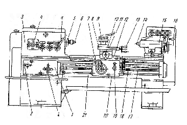 Fig. 47. Engine Lathe: Fig. 47. Engine Lathe:1 — feed gearbox; 2 — feed selection levers; 3 — headstock and gearbox; 4 -speed change levers; 5 — spindle; 6— live centre; 7 — sliding hand traverse; 8 – tool rest; 9 – tool post; 10 – cross-slide lever; 11 – compound rest; 12 – saddle; 13 – tool rest lever; 14 – dead centre; 15 – tailstock; 16 – electric motor; 17 – feed shaft; 18 – lead screw; 19 – sliding feed lever; 20 – apron; 21 – bed 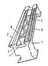 Fig. 48. Bed: Fig. 48. Bed:1,5 — ribs; 2, 7 — casting walls; 3, 6 — V-type ways; 4 — flat way The bed (Fig. 48) is a rigid casting with two longitudinal walls firmly connected by cross ribs integral with the casting. The bed serves as a base to support and align the rest of the machine. The upper surface of the bed is provided with parallel V-type and flat ways or guides for accurate aligning of the sliding parts of the lathe — the, carriage and the tailstock. The headstock is located and firmly bolted to the left hand side of the bed and carries a pair of bearings in which the spindle rotates. Many modern lathes have a motor built into the headstock with the spindle serving as the motor shaft. The spindle (Fig. 49), being one of the most important parts of a lathe, is a steel hollow shaft with a taper bore for the insertion of the live or running centre on which the piece to be turned is placed. The other end of the work is supported by the non-rotating dead or cup centre. The nose of the spindle is accurately threaded for chucks to be screwed on it. The chucks, in turn, hold and revolve workpieces together with the spindle. The head-stock also incorporates the change gearbox driven by a set of speed change levers. The change gearbox serves for running the lathe at different speeds required in turning and boring workpieces of various diameters. 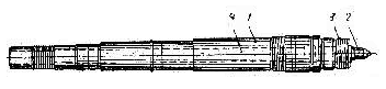 Fig. 49. Spindle: 1 — hollow shaft; 2 — live centre; 3 — thread; 4 — through hole The tailstock (Fig. 50) located at the right-hand side of the bed, is a casting carrying a non-rotating sleeve, which together with the nut can be advanced or retracted by means of the tailstock revolving screw operated by the handwheel. The tailstock may be moved anywhere along the lathe bed and can be clamped in place at any point. On changing the position, the tailstock slides along the two inner bed ways one of which named flat way is of rectangular cross-section and the other one is of V-section. The tailstock sleeve mounts a hollow spindle with a standard taper bore for holding the lathe centres or tapered tool shanks. The dead centre fits in a Morse taper hole in the sleeve and may be removed by retracting the sleeve, thereby bringing the end of the tailstock screw against the rear of the centre and forcing it out. The tailstock spindle has a large area bearing1 in both the front and rear of the tailstock. To facilitate measurement of the spindle travel the tailstock spindle is graduated. 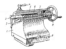 Fig. 50. Tailstock: Fig. 50. Tailstock: 1 — casting; 2 — tailstock clamping wrench; 3 — tailstock spindle centre; 4 — tailstock spindle clamp lever; 5 — revolving screw; 6 — sleeve; 7 -nut; 8 — tailstock handwheel; 9 — bed The feed mechanism for both longitudinal and cross feeds of the engine lathe is simple and easy to operate. It comprises a cone of gears, an intermediate shaft and a set of sliding gears. The fine change shifter slides on a splined shaft and carries a tumbler gear which is dropped into engagement with a gear on the cone corresponding to the thread or feed selected on the index plate above it. Movement of the carriage and the cross-slide can be reversed either by reversing the feed mechanism, with the reverse, handle or by shifting the single lever located on the carriage aprons. Suitable speed ratios between the spindle and the feed mechanism are provided by a change gearbox. The carriage is a unit intended for mounting the tool, and capable of sliding along the two outer V-type ways, on which it is supported, in a direction parallel to the spindle axis. For turning and facing operations the carriage is driven from the headstock spindle by gearingor belting through a feed shaft. For thread cutting, where a definite amount of carriage movement is required for every spindle rotation, a lead screw, geared to the spindle, is used for the motion of the carriage. The carriage is made up of two principal parts, one of which carries the saddle, which slides upon the bed and on which tine cross-slide and the tool rest are mounted. The other part, termed the apron, represents the front wall of the carriage. It provides a support for the operating hand-wheel and control levers, as well as carries the mechanism for engaging the feed mechanism of the lathe to drive the carriage. The cross-slide mounted on the carriage can move at right angles to the spindle axis. It is operated bythe cross-slide screw which turns in a nut fixed to the carriage. On the top of the saddle there is the compound rest for mounting the tool post. The compound rest is similar to the cross-slide, except that it can be swung around at an angle. It has a circular base graduated in degrees, so that it may be set at any angle, and may be used for cutting bevels, tapered work and similar jobs. The compound rest is actuated by a screw which rotates in a nut fixed to the saddle. The tool post intended for holding the tool fits in a tee slot in the compound rest, and the toolholder is adjusted, and clamped by the tool post screw. Engine lathes are fitted with a multiple disc clutch and brake. The powerful multiple disc clutch when disengaged automatically engages the plate brake. There are three important methods of holding and rotating work in engine lathes, which may be referred to as turning between centres, chuck work, and faceplate work. In turning between centres, the work is supported by the 60° conical points, of the live and dead centres. It turns together with the live centre on the dead centre. In chuck or faceplate work, the work to be machined is held in a chuck or a faceplate. ________________________ 1. large area bearing — подшипник с большой площадью опоры Exercises I. Use the following words and phrases in sentences of your own: bench lathe, turret lathe, to bore, engine lathe, carriage, cross-slide, rigid, bed, change gearbox, to revolve, sleeve, to advance, handwheel, to retract, feed mechanism, feed shaft, to actuate, feed, apron, to swing II. Retell the text giving answers, to the following questions: 1. What is a lathe? 2. What operations may be performed on a lathe? 3. What devices enable grinding and milling operations on a lathe? 4. With respect to what characteristic features are lathes classified? 5. What types of lathes are mentioned in the text? 6. What kind of work is the bench lathe intended for? 7. What are turret lathes? 8. Why are some lathes termed chucking lathes? 9. What are automatic lathes? 10. What lathes belong to special-purpose lathes? 11. What basic parts does the engine lathe consist of? 12. What is the function of the lathe bed? 13. What is the upper surface of the bed provided with? 14. What do the bed ways serve for? 15. Which side of the bed is the headstock bolted to? 16. What does the change gearbox serve for? 17. What is the tailstock and where is it located? 18. Which bed ways does the tailstock slide along? III. Choose antonymical groups out of the following list: dead centre, alignment, regular, right feed, fasten, disalignment, irregular, left feed, easy, to prohibit, unfasten, live centre, difficult, to permit IV. Change the sentences using the "Nominative with the Infinitive" and then translate them into Russian: Example: It is known that the lathe is the most important machine tool used for machining surfaces of a workpiece. The lathe is known to be the most important machine tool used for machining surfaces of a workpiece. 1. It is known that the lathe is regularly furnished with a multiple disc clutch arid brake incorporated in a driving pulley. 2. It is intended that the compound rest slide is actuated by a screw rotating in a nut fixed to the saddle. 3. It is known that, the headstock and the tailstock are fastened at opposite ends of the lathe bed. 4. It was said that the independent chuck had been suitable for almost any type of work. 5. It seems that this new feed mechanism is simple and easy to operate. 6. It proved that the functions of the new lathe were fully automatic. 7. It was evident that the engine lathe has been widely used for metal-turning operations. V. Make up questions to which the italicized words are the answeres: 1. The lathe is a machine tool for machining surfaces of a round workpiece. 2. The tailstock of a lathe rests on a saddle. 3. The lathes are generally furnished with brakes. 4. To start the spindle one can use either the head or apron control. 5. The cross-slide is mounted on the carriage. 6. The tool holder is clamped by the tool post screw. 7. The feed mechanism comprises a cone of gears, an intermediate shaft and a set of sliding gears. 8. The change shifter slides on a splined shaft and carries a tumbler gear. VI. (a) Read and translate the following text without using a dictionary: The automatic lathe is designed so that all of the tool movements are automatically controlled, although the work must be inserted and removed by an operator. In the automatic lathe two or more, heavy duty slides, each with its own drive, rate of feed and direction of feed, may be applied. All functions of the machine are completely automatic, including advance of the platen to working position, feeding of all tools, and retraction of slides and platen at completion of cycle, at which time stopping of the spindle is also accomplished, automatically. One operator may run two or more lathes. Such lathes are not limited to automative parts but are reducing production time and cost on pump parts, motor and generator parts, pipe flanges, brass and bronze castings, chuck bodies, bevel gears, airplane engine cylinders, etc. (b) Make up questions on the basis of this text and answer them. VII. Giving answers to the following questions describe the: construction of the spindle shown in Fig. 49 and the bed shown in Fig. 48: 1. What part of the lathe is a spindle and what purpose is it intended for? 2. What kind of shaft does a spindle represent? 3. For what purpose is a spindle supplied with a taper bore? 4. What has to be done with the nose of a spindle for the chuck to be screwed on it? 5. What does the lathe bed serve for? 6. What kind of walls is the bed supplied with? 7. How are the walls of the bed connected? 8. What is the function of the bed ways? VIII. Using the following words and word combinations describe the construction of the tailstock shown in Fig. 501 a casting, to consist, the tailstock, to be fitted to the bed, to carry, a non-rotating sleeve, to be advanced, the revolving screw, to operate, the handwheel, to move along the lathe bed, to be of the V-section, a hollow spindle of the tailstock sleeve, to be provided, a standard taper bore, hold the lathe centres, the tailstock spindle, to be graduated, to facilitate measurement, the spindle travel
Drilling machines are very old machine tools mainly employed for drilling holes of different sizes in metal or any other solid material. In addition to drilling holes, such operations as tapping, reaming, lapping, countersinking and counted boring may be performed on the drilling machines. Since drilling machines are used for a great variety of operations they fall into various classes, the main of them being upright or vertical spindle, multiple-spindle, and radial spindle chines. In all three types, the drill spindle rotates in a sleeve at quill which does not rotate but is free to move axially to provide the necessary feed for the drill. In vertical spindle drilling machines the spindle is in a vertical position. The upright drilling machine (Fig. 51) has an upright column resting on a heavy base. The column equipped with a gearbox providing a wide range of speed has a feed mechanism. The feed mechanism represents a feed shaft with its necessary gearing by which the drill is cut into the work at a proper speed. The feed shaft and the gearing provide a mechanical feed and any adjustment of both the drilling head mounted on the top of the column and the table for drilling operations. Since in the upright drilling machines the spindle sleeve supports are fixed, all adjustment for different classes of work is made by moving the table which is accomplished by turning the crank. The table can be moved in a horizontal plane, clamped at any point or, if desired, swung out of the way so that large work may be placed on the base. The machine is also equipped with a ratchet lever for hand feeding the drill. A handwheel is fastened to a worm shaft whoseworm engages a worm gear on the pinion feed shaft, giving a motion much finer than that obtained by using the hand lever. Speed changes in the upright drilling machines are effected either by cone pulleys or by a geared head. The upright drilling machines, in turn, are classified as: heavy duty, plain, and sensitive. The heavy duty drilling machine is used for heavy drilling the plain vertical spindle machine being employed for lighter work. The sensitive drilling machine is a vertical or upright machine of comparatively light construction adapted to very high speeds of drilling holes in delicate works.1 The multiple-spindle drilling machines are built in both vertical and horizontal types. Saving considerable time and space this machine is used for simultaneous drilling of many holes in a large number of workpieces. The machine may have a number of movable drills mounted on the cross way, all the spindles being driven from the same shaft by a worm gear. One of the types of the multiple-spindle machines is the fully automatic multiple-spindle drill head machine requiring only push-button 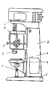 Fig. 51. Upright Drilling Machine: Fig. 51. Upright Drilling Machine:1 — table traverse lever; 2 — feed change lever; 3 — spindle; 4 — swarf tray; A — table; В — feed change gearbox; С — gearbox; D — column; E — base operation once it has been set up. The machine is provided with a large number of spindles ranging from four to a hundred or even more, which are driven by the same spindle drive gear in the same head. The radial drilling machine has a vertical column mounted on a cast iron base. The column carries a radial arm which moves not only in a horizontal plane with the column, but may also be moved in a vertical plane. A drilling head carrying the drill and power feed mechanism may be moved along horizontal ways of the arm. Bored to take a Morse taper shank, the spindle is driven by a reversing motor, flange mounted on top of the gearbox.2 The drill can be moved over the work to any desired position so that many holes may be drilled in the work without moving it from one place to another. The radial drilling machine is therefore adapted to heavy work where it is easier to move the drill than the work. Spindle speed and feed changes are effected by gearing. Drilling speeds may vary from 40 ft. per min3' for cast and alloy steels to 300 ft per min for brass and bronze, drillings feeds ranging from 002" per revolution for ________________________ 1. delicate works — хрупкие заготовки 2. Bored to take a Morse taper shank, the spindle is driven by a reversing motor, flange mounted on top of the gearbox — шпиндель, расточенный под конический хвостовик Морзе, приводится в движение реверсивным двигателем, а установочный фланец расположен на верху коробки скоростей. 3. ft. per min — foot (feet) per minute—футов в минуту Exercises I.Use the following words and phrases in sentences of your own: to tap, drilling machine, to ream, vertical spindle drilling machine, quill, to swing, crank, ratchet lever, radial arm, to accomplish, multiple-spindle drilling machine, sensitive drilling machine II. Retell the text giving answers to the following questions: 1. What operations may be performed on drilling machines? 2. How are drilling machines classified? 3. Where does the drilling machine spindle rotate? 4. How is the spindle sleeve moved? 5. What is provided by such a movement? 6. What are vertical spindle drilling machines? 7. What structural feature gives the upright drilling machine its name? 8. How is a wide range of speeds obtained on this machine? 9. What does the feed mechanism of the drilling s machine consist of? 10. What is the function of the feed shaft? 11. How can the table be moved? 12. What does the ratchet lever serve for? 13. How are speed changes effected the upright drilling machines? 14. When are the heavy duty drilling machines used? 15. What is the plain vertical s spindle machine employed for? 16. For what type of work is the sensitive drilling machine designed? 17. What are multiple-spindle drilling machines and what are they used for? 18. How many spindles may be used in a fully-automatic multiple-spindle drill head machine? 19. For what kind of work is the radial drilling machine intended? 20. What main к parts does the radial drilling machine consist of? 21. What range of spindle speeds and feeds may the radial drilling machine have? III. Give derivatives from the following words and translate them into Russian: to bore, light, sensitive, high, to construct, to employ, to vary, to provide, to move, to adjust, to drill, to revolve IV. Give different meanings of the following words: arm, head, work, way V. Translate the following sentences observing different meanings of the italicized words and word combinations: 1. Drilling means removing some metal from the work. 2. A drilling machine is by all means the most important machine for drilling holes of different size in metal. 3. By no means can a boring machine be used at speeds exceeding permissible ones, as it may result in breakage. 4. Boring may be performed on drilling machines. 5. The main driving motor drives the shaft by means of Vee-belts. 6. When we speak of the operations performed on the drilling machine, we such operations as tapping, reaming, lapping, etc. VI. Find the predicates in the following sentences. Translate the sentences into Russian: 1. The hydraulic sliding head is said to be actuated by a large diameter cylinder. 2. We know the hydraulic sliding head to contain the feed and rapid traverse hydraulic pumps. 3. The two work spindles are driven by heavy helical gears through pick-off gears for controlling the spindle speeds. 4. The main drive motor, mounted on top of the head, drives the main shaft by means of Vee-belts. 5. On the outside of the plate, there is a table showing spindle speeds and the proper pick-off gears to be used for the required speed 6. This machine may be used for boring operations in shorter cylinders. VII. (a) Read and translate the text without using a dictionary: A semi-automatic, vertical boring machine is designed to facilitate the machining of heavy components such way wagon wheels, with weights up to 700 lb. The has two hydraulically-operated 5-jaw chucks mounted on a table which can be traversed to bring either beneath the spindle.1 Power for operation, of the chucks, the movement of the table, and the feed of the spindle, is supplied separate unit. The spindle is 7 ft long, and is supported taper roller bearings at the top and one at the lower end. It is driven by a 75-h.p. variable motor, and speeds suitable for a variety of bore sizes can be obtained. The boring bars are fitted with throw-away carbide inserts,2 which clamped in position, two square roughing and two cylindrical semi-finishing tools being arranged alternately, 90 deg. apart. A surface speed3 of 225 ft per min is normaly employed the spindle is fed at the rate of _________________ 1. to bring either beneath the spindle — для того чтобы подвести каждый из этих патронов под шпиндель 2. throw-away carbide inserts — сменные карбидные вставки 3. surface speed — скорость резания (b) Retell the text. VIII. Using the following words and word combinations describe all drilling machines that you know: drilling machines, to be old machine tools, to employ, drilling holes, operations, tapping, reaming, and lapping, to be performed, to fall, various classes, upright spindle drilling machines, to have the spindle, to be placed, a vertical position, to be classified, heavy duty, plain and sensitive machines, multiple-spindle drilling machines, to be provided, a large number of spindles, to be used, simultaneous drilling, many holes, the radial drilling machine, to have л vertical column, to carry a radial arm, to move in a horizontal and vertical planes, the drill, to be moved over the stationary work, any position, to be adapted, heavy work IX. Describe the principle of operation and construction of the radial drilling machine shown in Fig. 51. 3. MILLING MACHINES Milling machines are used for milling operations. Milling is the process of removing material from work with a multi- toothed rotating cutter. There are various classes and types of milling machines in use, from small hand-operated types to fully automatic ones, the main of them being: columnand knee-type, bed type, planer type, and rotary type. Column-and knee-type milling machines are made in three styles:horizontal plain, vertical and universal spindle milling machines. They are used for both toolroom and manufacturing work because of the ease with which they may be handled. Fig. 52 shows the essential features of the horizontal miling machine. The machine is provided with a massive stream-lined column rising from a base which rests, on a solid wooden or concrete floor which is sufficiently heavy to withstand the weight of the machine. The base, hollow inside contains a coolant tank with cutting fluid* that is delivered through piping by means of a motor-operated pump to the cutters and the place where the milling operation is performed. The centrifugal type pump is mounted on the pad located at the side of the base and is connected directly to the coolant tank. The cutting fluid flow can be regulated by means of valves connected to the outlet nozzles whichcan be swiveled for distributing a low pressure volume of cutting fluid to all diameter and types of cutters. A constant supply of clear oil is pumped to the column top, distributed through perforated pipes and flooded down over all gears, shafts, and bearings throughout the entire column and feed gearbox. In the lower part of the column there is a motor for driving the spindle and the change 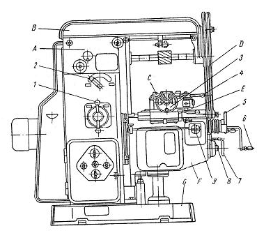 Fig. 52. Horizontal Plain Milling Machine: A —column with speed gearbox and spindle unit; B — overarm; С — table; D — additional link between knee and overarm; E — saddle; F— knee with feed gearbox; G – base; 1 – gearbox change lever; 2 – spindle speed change lever; 3 — longitudinal feed table handwheel; 4 - longitudinal feed table lever;5 — cross feed table handwheel; 6— vertical feed knee hand lever; 7 – feed gearbox handwheel; 8 — gear train lever; 9 — vertical-cross feed table lever gears for the power feed, к set of change gears for driving the spindle at a proper speed required for any work being done on the machine is housed in the upper part of the column. The change gears are shifted either manually by a spindle speed ____________________ * American — cutter coolant change lever located on the face of the column or by power to form various trains for providing the necessary cutting speeds. The horizontal plain milling machine has a horizontal spindle rotating in anti-friction bearings in the column. The spindle is a hardened, ground, hollow shaft spaced horizontally from the front to the back of the column. In operation, the milling cutters are either attached to the spindle nose or carried on an arbor. Secured to the top of the column is an overarm consisting of one or two heavy steel bars. The overarm is provided with bearing brackets for supporting arbors or mandrels. The knee which supports, the table and saddle units is mounted on the face of the column and can be moved up and down by means of an elevating screw for adjusting workpieces with respect to cutters. During each milling operation the knee should be clamped to the column, and in heavy-duty operations the knee is clamped to the overarm to ensure maximum rigidity. The upper part of the knee is provided with horizontal dovetail guides, which support the saddle unit mounted on them. The saddle, in turn, supports the table which is a heavy, semi-steel casting1 sliding in the dovetail guides on the saddle. The table has T-slots of ample depth serving to fasten work-holding devices. All the three elements, table, saddle, and knee, may be either power- or hand-fed by screws turning in fixed nuts. By means of a hand lever on the knee, the machine can be set for continuous pendulummilling, orfor automatic cycle operation, with power feed movement of the table in either direction. The machine is provided with a backlash eliminator, which enables climb milling to be performed with both right- and left-hand cutters and is automatically disengaged upon reversal of the table. The eliminator can also be disengaged by movement of a lever when conventional milling is to be performed. Vertical milling machines are similar to plain milling machines, but their spindle is positioned vertically. Universal milling machines are also similar to plain milling machines but the saddle is mounted on and swivels on a clamp bed which in turn slides on the knee thus permitting the saddle to swing at an angle, and permitting table motion at other angles than 90° to the spindle axis. Modern heavy-duty milling machines are equipped with a standardized spindle end which has a locating taper hole in the spindle. The arbor is seated by turning a draw-in-bolt2 which extends through a hole in the spindle, and screws into a threaded hole in the arbor. The arbor is driven by an adjusting key on the spindle nose which fits into slots in the arbor shoulder. The arbor support provides a cylindrical bearing for the pilot of the arbor, and in many instances, an intermediate arbor support, serving as a bearing for an oversize collar,is employed. The arbor support is often connected to the knee by overarm braces for additional rigidity. Cutting speeds on the milling machine depend upon the nature of the work, the type of cutter, the condition of the machine, and, in many instances, upon the experience and ability of the machine operator. Feed rates in milling are expressed in two ways: in. per min,3 or thousandths of an inch per revolution of the spindle. Delicate or fragile work requiring an accurate finish will need fine feeds, while heavy work, from which a considerable amount of metal is to be removed, can be subjected to coarse feeds. A good finish can usually be obtained by using a feed rate from 0.30" to 0.50" per revolution of the cutter. Finer feeds, such as 0.15" per revolution, will result in an excellent finish. _________________ 1. semi-steel casting — отливка из сталистого чугуна 2. the arbor is seated by turning a draw-in-bolt — оправкам устанавливается поворотом втяжного стержня 3. in. per min — inch per minute — дюйм в минуту Exercises I. Use the following words and phrases in sentences of your own: cutter, milling machine, column, knee, cutting fluid, power feed, fine feed, to swivel, pump, to house, elevating screw, to adjust, to clamp, overarm, feed rate II. Answer the following questions: 1. What is milling? 2. What are the main types of milling machines? 3. How are column- and knee-type milling machines classified? 4. What does the base of the plain milling machine serve for? 5. By what, means can the cutting fluid flow be regulated? 6. What is located in the lower part of the column? 7. What is housed in the upper part of the column? 8. What can you say about the spindle of the horizontal plain milling machine? 9. What is secured to the top of the column? 10. What is supported by the knee? 11. By what means can the knee be moved up and down? 12. Why should the knee be clamped either to the column or to the overarm during, each milling operation? III: Find in the text antonyms of the following words to raise, light, to be unfixed, fine feed, back, lower part IV. Underline the suffixes arid prefixes and translate into Russian the following words: principle, principal; long, longitudinal; horizon, horizontal; to obtain, obtainable; automatic, automatical, automatically; to cut, cutting, non-cutting; convention, conventional; dependent, dependency, independently V. State the kind of the subordinate clauses in the following sentences and translate them into Russian: 1. The profile of the teeth on the pinion is identical with the straight line profile of the teeth of a rack that meshes with the generated gear. 2. In the same way as one and the same rack will mesh with gears of different pitch diameters (number of teeth), but of identical diametral pitch, one and the same hob can be used to hob all gears of identical diametral pitch regardless of the number of teeth on the gears being hobbed. 3. The fact that the hob form nearly approaches a straight line rack tooth shape is a fundamental advantage of the hobbing process, because the hob teeth being straight-sided or nearly so, are readily made to a high degree of accuracy and are easily measured, as compared with curved cutter teeth in other methods of gear cutting. VI. Make up questions to which the italicized words are the answers: 1. The milling machine is a machine for removing metal from the workpiece. 2. There are horizontal, vertical and , column knee milling machines used in practice. 3. The knee is mounted on a vertical guide. 4. The saddle slides from front to back on guides. 5. A maximum distance of 15 in is obtainable between the spindle axis,, and the working surface of the table. VII. Translate the following text in written form without using a dictionary: |