AГЛИЙСКИЙ. Пособие по английскому языку для машиностроительных вузов допущено Министерством высшего и среднего
 Скачать 1.36 Mb. Скачать 1.36 Mb.
|

THE UNIVERSAL MILLING MACHINEThe cutter spindle is large in diameter, hardened and ground, and has double opposed bearings on the front end. The back end is mounted on ball bearings which are so arranged that compensation for expansion is provided. A ram type overarm with double angle bearing on the ram overarm ways, provides rigid support for cutters and attachments. The column has added way length for securely holding the ram unit. The base contains a coolant tank. The knee is massive in size to provide the greatest support for the table and saddle units. The entire feed change transmission unit is contained in the knee, and is operated through the vertical drive shaft from the drive unit located in the base and column. Dependable automatic lubrication ensures an adequate supply of oil to all moving parts. VIII. Using the following words and word combinations describe the principle of operation and construction of the horizontal plain milling machine shown in Fig. 52: the horizontal plain milling machine, to be provided, a column, to rise, a base, to rest, a concrete floor, the lower part of the column, to incorporate, a motor, to drive the spindle and the change gears, the upper part, to house a speed gearbox, a proper speed, an overarm, to consist, one or two heavy steel bars, to be secured, the top, the knee, to support the table and saddle, to be mounted on the face, to be moved, up and down, an elevating screw, to adjust workpieces, cutters, work-holding devices, to be fastened, T-slots, cutting speed, to depend upon the nature, the work, cutting 4. PLANERS Planers like shapers and slotters are machine tools that employ single-point tools to generate flat surfaces. In each of these the relative motion of the cutting tool and the work is rectilinear and either the tool or the work feeds in a direction perpendicular to the cutting strike. All three machines finish surfaces in a similar manner, and their selection depends primarily upon the nature of the work. The planer is generally used for machining large work requiring long cuts. The work is held on a horizontal table and moves back and forth past a stationary tool. The planer is also known to be used when a large number of like parts are to be finished, tin this case the parts are frequently placed on the planer table in rows, and a number of parts are planed at one setting. This operation is referred to as string planing. Planers and shapers are used for machining surfaces to a high degree of accuracy, and in general require less power per cubic inch of metal removed than machine tools employing multi-toothed cutters. Planer and shaper tools are con- 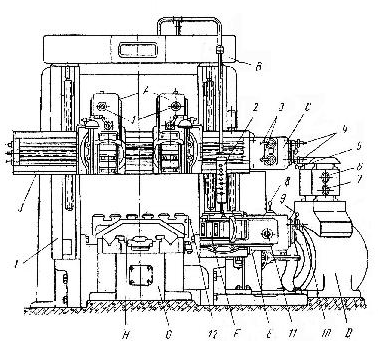 Fig. 53. Double-Housing Planer: A — tool tests; В — portal; С — tool rests feed gearbox; D — cutting drive; E — side rest feed gearbox; F — side rest; G — bed; H — table; I — two vertical housings; J – cross rail; 1 – vertical feed tool slides quadrant; 2 – pendant control; 3 – tool rest feed change levers; 4 – horizontal feed tool rest quadrant; 5 – tool rest feed lever; 6 – working speed table handwheel; 7 – idle travel hand wheel; 8 – vertical feed change side rest lever; 9 – side rest feed lever; 10 – feed side rest lever; 11 – horizontal feed side rest lever; 12 – supports siderably less expensive than milling cutters; the planer may therefore be used in preference to a milling machine if the castings are poor and subject to hard spots.1 There are several standard types of planers that are in extensive use in jobbing and production shops such as double-housing planers; open-side planers; tandem planers, and rail planers. The double-housing planer (Fig. 53) has two vertical housings and is used for rapid roughing and finishing such works as engine and lathe beds, etc. Ample strength and support of the housings are assured by their thick-walled, box-section internal bracing. The housings are keyed and bolted to the bed, forming a unit apt rigid as a one-piece construction. The large-size planer of this type is provided with two cutter heads* mounted on the cross-rail. The heads serve for holding two tools, which may cut material simultaneously, thus increasing the work capacity of the planer. In a planer with two cutter heads both vertical and side feeds,** being independent of each other, are performed automatically. In addition, some planers are equipped with a side-head mounted on each housing. This arrangement makes it possible to machine simultaneously both the side and the top surface of a work to be treated. The work to be planed is bolted or otherwise securely fastened to the table. The table is made of alloy iron and is оfa box-section construction with top and bottom plates tied with side walls and the centre rib running the full length2, and with cross-ribs. The upper part of the table has three оr more tee slots running lengthwise, and numerous holes for inserting stops and clamping blocks, while the under side is provided with two accurately machined guides which slide in guide ways on the planer bed. The table moves between two housings against one or more cutting tools, which are held by the cross-rail and side-heads screwed to the housings, at a speed adapted to the material to be cut. The return stroke, during which no cutting takes place, is usually constant, but is from two to four times as fast as the cutting stroke so as to economize on time.3 Planer size is determined by the maximum stroke of the table and the width and height of the work that will pass through the housings and underneath the cross-rail. A double housing 36x30x8 planer, for instance, will machine a part 30" high, 30" wide and 8" long. Op en-side planers are classified by the cross-rail height and the length of stroke, and are generally used for handling work that is somewhat wider than its height. The open-side planer has but one vertical housing4 with the cross-rail attached to it. The tandem planer is equipped with two work tables sliding4 on the same bed. This permits to load one table while the other is in operation, or to use the two simultaneously when working on a large workpiece. The rail planer is a machine used for machining rails, which is provided к with a narrow long table. Planer work may be held in a vice bolted to the planer table. Planer work may be clamped directly to the table. Castings can generally be damned in place5 by using straps or clamps on projecting portions of the work. All planers are equipped with single-point cutting tools, which are similar to shaper tools, but are usually larger and stronger. In many cases, gang planer tools, carrying three or more tool bits closely adjacent, are used. As each chip is comparatively small, a planer equipped with a gang tool will carry a far greater total feed and depth of cut than are possible with a single-point tool. _____________________ 1. If the castings are poor and subject to hard spots — если отливки плохие и имеют твердые места 2. the centre rib running the full length — центральная поперечина, проходящая по всей длине 3. but is from two to four times as fast as the cutting stroke so as to economize on time — но в два—четыре раза быстрее хода резания, для того чтобы сэкономить время 4. has but one vertical housing — имеет только одну вертикальную стойку 5. castings саn generally be clamped in place — отливки обычно могут закрепляться на месте ___________________________ * American — cutting head ** American — lateral feeds Exercises I. Use the following words and phrases in sentences of your own: planer, rail, housing, stroke, rectilinear, machining, work table, brace, slot, cross-rail, side-head, to employ, to cut, to plane, to equip, to bolt, arrangement, adjacent, gang planer tools II. Answer the following questions: 1. What is a planer? 2. What is the planer used for? 3. Where is the work to be treated on the planer held? 4; What is string planing? 5. Name the main types of planers. 6. What is the main feature of the double-housing planer? 7. By what is ample strength of the housings assured? 8. What are the housings keyed and bolted to? 9. How many cutting heads are the large-size planers provided with? 10. What are the cutting heads mounted on and what are they used for? 11. What operations is it possible to carry out on planers provided with side-heads in addition to two cutting heads mounted on the cross-rail? 12. What is the work table designed for? 13. What is the construction of the table and what is it made of? 14. How does the work table move? III. Give derivatives from the following words and translate-them into Russian: relative, to move, to machine, to plane, to attach, rough, flat, brace IV. Give different meanings of the following, words: plane, head, rib, poor, bed, table, unit, plate, house V. Supply synonyms for the following words: surface, to mount, fast, accurate, speed, to determine, wide VI. Supply antonyms for the following words: flat, vertical, open, narrow, fast, high, hard, long, large, heavy VII. Find the predicates and state the kind of the subordinateclauses in the following sentences and translate into Russian: 1. A tool apron extends the full width of the slide and is provided with horizontal T-slots running the full width of the apron so that tool holding bolts may be laterally adjusted to properly hold the tool. 2. This construction allows the greatest variety of possible tool positions and, therefore, greatly reduces the number of tool shapes required. 3. The tool frame supporting the tool apron swivels 20 degrees, either side of the centre. 4. Index plate swivels on a large bearing which is cast integral with the index, thus giving added stiffness to the index and providing the most rigid construction for resisting the cutting strains. 5. All controls are so completely centralized that the operator can run the entire machine, except for the left-hand side-head, without moving from his normal working position at the end of the cross-rail. VIII. Make up questions to which the italicized words are the answers: 1. The planer is a machine for producing flat surfaces on a work. 2. The entire drive from motor to work consists of three gears and one rack. 3. The bed is the strongest construction of the planer. 4. Cross-ribs tie the housings together. 5. The design of the table ways is of great importance. 6. The table is made of alloy iron. 7. The rack is set in a groove machined in the table. IX. (a) Read and translate the following text without using a dictionary: The entire drive from motor to work consists of only three gears and one rack. Helical gears are steel, and the spiral gear and rack are both made of high strength alloy iron but of different analysis and hardness so as to provide a combination of materials unsurpassed for strength and wearing qualities. Spiral gear is an involute gear, while the table rack is an involute rack, and the action between them is equivalent to the action of an infinite number of spur gears and Tracks. This is the reason why it is the smoothest of all planer drives and it never wears out but always wears in.1 The rack teeth are cut at an angle so that the resultant tool pressures are parallel to the line of motion of the table. This entirely eliminates driving side thrust on the table. ____________________ 1. it never wears out but always wears in — никогда не изнашивается, но всегда прирабатывается (b) Make up some questions on the basis of the text and answer them. X. Using the following words and word combinations describe the principle of operation and construction of the double housing planer shown in Fig. 53: the double-housing planer, two vertical housings, to be used, rapid roughing and finishing, such work, engine and lathe beds, strength and support, the housings, to be provided, internal bracing, to be keyed and bolted, the bed, top form, a rigid unit, two cutting heads, to be mounted, the cross-rail, to hold tools, to cut material simultaneously, the work, to be planed, to be secured, the table, to be made, alloy iron, to have, top and bottom plates, to be tied together,side walls, centre rib, cross-ribs, the upper part, three ormore tee slots running lengthwise, numerous holes, to insert stops and clamping blocks, the under side, two accurately machined guides, to slide, guide ways, to move, against one or more cutting tools, to be held, the cross-rail and side-heads, the return stroke, to be constant, no cutting, to take place 5. SHAPERS AND SLOTTERS Shapers and slotters are machine tools in which the work is fed to a reciprocating tool, while in planers the tool is, fed to the work. The shaper is mainly designed to plane horizontal surfaces, but it is also possible to finish vertical and angular surfaces, and, with the application of the proper tools, even curved surfaces of workpieces of small and medium sizes. The slotter, which may be called a "vertical-shaper", since its tool moves in a vertical direction past the stationary work, is used for machining flat surfaces which are difficult or inconvenient to machine because they are at right angles to the main dimensions of the part. The slotter is also employed for cutting internal keyways, square holes and die openings. Both the shapers and slotters are not used in mass production1 since they are rather slow in operation. The size of the shaper is determined by the maximum stroke of its ram. The largest standard shaper has a stroke of 36 in. That is why the shaper is employed to perform planing operations on comparatively small work, the planer being used on large work. Shapers are driven by belt from a countershaft, by direct connected motor, or by hydraulic power. When driven by motor, the power from the motor is transmitted by a belt or silent chain to the speed box drive shaft. Shapers (Fig. 54) are subdivided into several classes such crank-driven shapers, gear shapers, universal shapers etc. The crank-driven shaper or crank shaper derives its cutting motion from a pivoted lever, which is driven by an adjustable crank. The shaper has a hollow column rising from a base placed on the floor. The column houses a part of the drive mechanism for the machine. Mounted 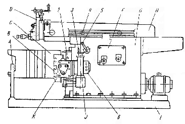 Fig. 54. Shaper: Fig. 54. Shaper: A - column; В - cross-rail; С - table; D - tool rest; F – tool rest drive; G – bed; H – ram; I – base; J – feed drive; K – table feed mechanism; 1 – tool rest lever; 2 - tablefeed change lever; 3 – feed change handweel; 4 – longitudinal feed ram clamp; 5- ram feed change lever; 6 - pendant control on the front of the column, which is machined so as to provide vertical bearing surfaces, is the cross-rail. The cross-rail, together with the saddle and the table which it supports, may be adjusted up or down for various heights on the face of the column with an elevating screw. The box-section table which is designed to carry the work is fastened to the front of the saddle, and feeds in a direction perpendicular to the tool motion. The table is provided with T-slots on the top and sides for clamping the work. The work may be clamped either by means of bolts, or in a vice which are held in the T-slots. A swivel-base vice being mounted on the top of the shaper table, the vice may be rotated about a vertical axis to set workpieces at an angle in the horizontal plane. The top of the shaper column is machined to form ways for supporting and guiding a ram which can slide along these ways forward and backward both in a cutting and return stroke cycle. The ram supports a tool head mounted on the front end of the ram, and a toolslide with a swivel base. The tool head carries the downfeed mechanism for the tool. The downfeed median ism consists of a lead screw and a handle for feeding the clapper box, mounted on the toolslide, and the tool up and down by hand. In addition to the hand downfeed, most shapers are equipped with a power downfeed. The tool head can swivel about the centre of the ram to enable the tool to be; fed at an angle. Owing to the swivelling of the clapper box on the tool head the tool may be inclined at an angle with the head in any position, the angular adjustment of the clapper box being smaller than that for the tool head. A tool post for holding the cutting tool is mounted in the clapper box. Shaper tools are similar to solid or inserted-bit lathe tools; extension tools are used for cutting keyways and square and splined hales. Since the shaper tool acts only during the forward stroke of the ram and is idle during the return stroke, it is necessary to minimize this idle time by using a quick return mechanism. The mechanism represents a variation of a driving chain, which is one of the most common of linkages.A pinion engages a large gear to which is affixed a crank arm. The outer end of the crank is pinned to a slide block, which is free to slide on a long swinging arm. As the crank revolves, this arm oscillates back and forth, and by means of yoke reciprocates a table on suitable ways. The work to be shaped is clamped to this table. The point at which the oscillating arm is tangent on either side to the crank pin circle separates the cutting from the return stroke. Since the crank arm turns uniformly, time is proportional to crank angle. The return stroke is accomplished in a much smaller crank angle than the cutting stroke, and consequently consumes less time. Gear shapers are special machine tools used for machining gear teeth. Universal shapers are equipped with tilting or adjustable tables which maybe set at an angle toward either side of the machine. _________________ 1. mass production — поточное (или серийное) производство Exercises I. Use the following words and phrases in sentences of your own: shaper, slotter, to machine, speed-box, ram, swivel-base vice, tool slide, clapper box, downfeed mechanism, to incline, splined holes, to pin, slide block, to oscillate, quick return mechanism II. Answer the following questions: 1. What are shapers and slotters? 2. What are they used for? 3. Why are shapers and slotters not used in mass production? 4. What is the size of the shaper determined by? 5. By what means are shapers driven? 6.What classes are shapers subdivided into? 7. What is housed in the shaper column? 8. What part of the column is the cross-rail mounted on? 9. How does the table move? 10. What is the table provided with? 11. What is the function of the ram? 12. Describe the features that characterize the downfeed mechanism. 13. During which stroke of the ram is the shaper cutting tool idle? 14. What mechanism is used to reduce the idle time to minimum? 15. How are universal shapers distinguished from crank shapers? III. Give derivatives from the following words and translate •them into Russian: to reciprocate, to apply, to shape, to direct, to rotate, hydraulic, to subdivide, high, to oscillate, point, proportion, horizon IV. Find in the text English equivalents of: поперечно-строгальный станок, установочный винт, ползун, ход ползуна, салазки, перпендикулярный, приводить в движение, резцедержатель,механизм вертикальной подачи V. Make up as many questions as possible to the following sentences: 1. By means of shapers it is possible to machine flat sufaces of work. 2. Tool heads are clamped in any angular position by means of single control head locks. 3. Circulatory pressure system continuously lubricates ram guides. 4 A steel safety guard for ram is attached to the rear ofthe frame. 5. The cross feed to the table is actuated by a singly cam. VI. Describe the principle of operation and construction the shaper shown in Fig. 54 using the following words and word combinations: shapers, to be designed, to plane horizontal surfaces, the application, proper tools, to be employed, to finish vertical and angular surfaces, the crank shaper, to be shown, to сonsist, the following main parts, a hollow column, to house a part of the drive, mechanism, a cross-rail, to be mounted the front of the column, a saddle, a table, the latter, to be provided, T-slots, to clamp the work, the top of the shaper column, to be machined, to form, ways, to support, to guide, a ram, tool head, toolslide with a swivel base, a tool post, to hold the cutting tool, to be clamped, the clapper box 6. GRINDING AND GRINDING MACHINES A surface finishing process, that is removal of irregularities from machined surfaces, may be performed either by employing hardened steel tools in such operations as filing scraping and burnishing, or by employing abrasives for surface refinement in grinding, lapping, honing, superfinishing and polishing operations. Grinding is the process of removing metal very accurately and economically by means of solid or sectional abrasive wheels rotating at a comparatively high speed. Originally employed for sharpening tools, grinding has become a useful and accurate finishing process for both hardened and unhardened metal parts, especially in the mass production ofprecision parts. By means of grinding, articles made of hard material, can be brought to a true finish with very close tolerances. Surface finishing operations involving the application of abrasives of smaller size than those used in grinding are known as lapping, honing, superfinishing and polishing. In all these operations only a small amount of metal is removed in surface finishing. Lapping is used for accurate fitting many machine tools and mating parts. The process consists of rubbing their surfaces together under load, a very fine abrasive material being placed between them. The surfaces are rubbed until all their irregularities are removed and the surfaces fit closely. Honing is employed for producing a very fine finish by using a tool referred to as a hone. Hones of special shapes used for finishing internal surfaces of cylindrical work may contain several abrasive blocks, which can be moved out from the axis thus giving the tool any desired diameter. Superfinishing is a finishing process which brings metal to an extremely smooth surface by using a bonded abrasive stone held in contact with the work under low pressure. The work rotates against the stone at low speed, at the same time the stone being given a random motion. Grinding is performed on machine tools known as grinding machines, which use rotating grinding or abrasive wheels for producing cylindrical, conical, or flat surfaces. Many different types of grinding machines have been developed for grinding various kinds of work. The grinding machines are generally classified into several groups: bench grinders used for tool sharpening and general off-hand grinding usually consist of a motor with a two-wheel spindle replacing the motor shafts cylindrical grinders are used for grinding cylindrical and conical work. They are essentially similar to engine lathes, but the carriage and tool post are placed by a wheel stand carrying a grinding wheel. Internal grinders are grinding machines used for finishing internal surfaces of cylindrical or conical shape. Centreless grinding machines used for external cylindrical grinding have no centres to support the work, and the part to be ground is held on a work rest between the grinding whее1and a suitable regulating or feed wheel which imparts axial motion to the part. Internal centreless grinders are employed for finishing roller bearing races and bushings. Disk grinders used for plane surfacing operations are similar to bench grinders, but are equipped with metal disks to which abrasive disks are connected. Universal grinders can perform both internal and external grinding of cylindrical and conical surfaces. Surface grinders (Fig. 55) are designed for grinding flat surfaces. Machines of this type are divided into two groups: planer-type surface grinders whose table is rectangular in shape and traverses under the wheel, and rotary type surface grinders whose table is circular in shape and rotates under the wheel. The surface grinder has a 18 by 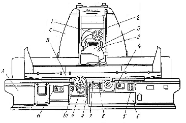 Fig. 55. Surface Grinder: A — bed; B — table; С — post; D — grinding head; E — hydraulic drive; 1 — head transverse feed handwheel; 2 — head transverse feed lever; 3 — diamond grinding wheel lever; 4 — head cross feed lever; 5 — pendant control; 6 — table speed lever; 7 — table reverse feed lever; 8 — table traverse-reverse lever; 9 — head vertical eed handwheel; 10 — head vertical feed knob; 11—magnetic plate lever movement, but the table can be traversed slowly under the control of a separate lever or handwheel, for example, when wheel dressing is to be carried out. A cross travel of Grinding wheels consist of abrasive grains held together by some bond such as clay, shellac; or rubber. The hardness of the abrasive, the shape and form of the grain structure and the tenacity of the bond are each important in grinding operations. The grade of a grinding wheel denotes its hardness, which cannot be accurately determined-by bond mixture or the, method of manufacture. Wheel grade is often indicated by letters, running from E, soft, to Z, extremely hard. Grinding wheels are dressed or trued by metal "star" wheels or by mounted diamonds1 to remove metal particles or dull grains of abrasive, and to restore their original shape and accuracy. ______________________ 1. grinding wheels are dressed or trued by metal "star" wheels or by mounted diamonds—шлифовальные колеса правятся металлическими звездочками или установленными алмазами Exercises I. Use the following words and phrases in sentences of your own: honing, superfinishing, lapping, wheel stand, grinding wheel, surface grinder, internal grinder, refinement, hone, abrasive wheel, to refine, to grind, to dress, to bind, to impart, work rest, lever, handwheel II. Answer the following questions: 1. What is grinding? 2. Why is grinding widely used in the mass production of precision parts? 3. What is lapping? 4. What finishing operations can be performed by employing abrasives? 5. What is honing and what tools are used in honing operations? 6. What is superfinishing? 7. What is the main feature of grinding machines? 8. What are bench grinders used for? 9. For what type of work is the cylindrical grinder used? 10. What types of grinding machines are used for finishing internal surfaces of cylindrical or conical shape?11. Why are centreless grinding machines called so? 12. For what kind of work is the internal centreless grinder adapted? 13. What are disk grinders equipped with? 14. What operations can be performed on the universal grinder? 15. What type of work is the surface grinder designed for? III. Supply synonyms for the following words: to mount, to rotate, to equip, to finish, circular, to deliver IV. Supply antonyms for the following words: to clamp, to stop, high, hardened, coarse, continuously, accurate V. State the kinds of sentences and subordinate clauses, find the predicates and translate the sentences into Russian: 1. In the case of surface grinding where the work is ground dry it is necessary to keep the wheel sharp and true if the grinding operation is to be done efficiently. 2. The ground diameter of the work is determined by the distance between the surfaces of the two wheels, while the work support acts as a third point of contact. 3. Since the work done on internal grinders in tool rooms is generally ground dry, these machines have to be built more accurately than other grinders, because it is harder to protect the most important parts from ever present abrasive dust and because the wheel and work speeds are much faster. 4. Lapping is a cutting process, while polishing consists of producing a kind of plastic flow of the surface crystals. 5. The abrasive particles are so hard that they will cut even hardened steel. VI. Make up questions to which the italicized words are the answers: 1. Surface grinding machines are divided into two groups. 2. In the surface grinders grinding wheels of different shape are used. 3. A precision grinding machine comprises a wheel, a wheel spindle, a work head and a work table. 4. The upper part of the work table can be swivelled about a vertical axis relative to the power part. 5. An abrasive wheel is composed of a large number of abrasive particles held together by a bonding material. 6. Surface grinding is the process of producing and finishing flat surfaces by means of a grinding machine using a revolving abrasive wheel. VII. Translate the following text in written form without using a dictionary: The wheel-slide plate control permits the grinding of straight, taper or irregular-shaped holes to a high degree of accuracy. The control plate or bar is set parallel to the work axis for straight-hole grinding, and adjusted to the desired angle for taper grinding. For grinding curved or irregular shapes, the plate is adjusted to suit the contour of the work. To traverse the wheel, the slide bar is moved longitudinally in its bearings, the path through which the wheel travels being controlled by the position and outline of the control plate. The control bar is carried in an adjustable bracket graduated in degrees. For taper grinding the clamping screws are released and the bracket is set at the desired angle. The wheel slide is attached to the slide bar and the latter is reciprocated by a double-acting hydraulic cylinder integral with the overhead slide bar. VIII. (a) Read and translate this text without using a dictionary: |